Thursday, 13 March 2014

Massacre Build 4

Ok this post might get a little hefty so I'll try and just use pictures to show what is going on. I did the super-giganto-mega-uber order of misc stuff for Massacre. I always for get just how much stuff robots need. Shit like bearings and bolts just seems to get left out of the costing ( and weight calculations) Totally professional, me.

First off I set about doing some of the work on the main bulkheads of the thing. Because I am not the greatest designer in the history of things, I had basically mounted half the components inside other parts and the whole setup is extremely mill intensive. *sigh* This is the part where I realise past Harry who did the CAD sort of forgot how real life works. Anyway, here are the blank side bulkheads before I did any more machining on them.


Marked out the aluminium in a ever so slightly ghetto fashion as I am prone to go, and then got cutting metal!

One side done, and the other side has an idiot proof encouragement sign on it, to prevent buggering up material/robot/hopes and dreams.


One of the bulkheads with the finger joint done on the back and the recess milled. I did this all with a 12mm endmill as I didn't have a 5/8" endmill in my bucket of odd imperial tooling.


More parts. Rubbishy photos due to this being quite late evening and me generally taking naff pictures.


Pretending to be a real robot. Also in this picture you can see random lump o metal, a battery operated soldering iron and a sky themed robot kindly donated by Joey. Who is six parts wonderful, incidentally.

And this is where the post started coming. It was like Christmas, except with less socks and more bushings.


Shaft collars, roller bearings, bushings, ball bearings of all sizes, threaded inserts, BOLTS, 24v LED's and a thrust bearing. Oh and a fair amount of silicone wire.


The reasoning for why I have both bushings and bearings will be explored shortly, although the conclusion is not at all justified/satisfactory to any sane human being. The brass things are 3/8" UNF nuts which are the same thread as drill motor shafts. I plan to heat press these into the nylon hubs that Ellis made for me to make totes legit wheels. The bolts are high tensile M8 and M5, 40mm long for assorted Massacre construction.


 Heat pressing happened and happened fairly well I thought. Nobody was even slightly on fire, which is always a good sign when blowtorches are used near Harry.


Mocking up seems to be a good 60% of what I do when I try and build robots. Here you can see the horrible milling that happened on the back panel and the vague wedge shape.

Continuing with the theme of post and packages, more stuff arrived the next day and some very exiting stuff it was too. First up was this mysterious package that had some crazy foreign writing and the inability to spell names on it. Bet it was that tricksy hobbit Elvis.


It's so shiny I'm gonna dieeeeeee. Yes its a yummy 6082 pulley/hub custom made for Massacre. Great stuff. How massive this is in the CAD and how tiny it feels in my hands makes me feel a bit uncomfortable...


Ok now we talk about the bearing/bushing situation. Basically I couldn't pick. The bushings are much more tough so that would be good for the weapon, but at the same time would have more resistance. Bearings are smoother but weaker. CHOICES HOW DO I.

Yep, that works. I managed to find bushings and bearings that had the same id and od, although different lengths but not by much. They fit the pulley nicely. Sweet.


And here we have some uninteresting visual stimulus. My big fuckoff bolts for the weapon, 12.9 high tensile cap head M10's. Six of those should keep the bar attached to the hub. Also featuring are some XT90 connectors I picked up for a few quid on eBay. These are for the removable link. They are large enough to take the current of the system but are fairly difficult to pull apart, a desirable quality.


A mysterious bar shaped package appeared! I wonder what it is? Maybe its a really heavy and ornate hat?


Nope chuck testa! Its a rather large, rather fancy hardened steel bar. Big thanks to Mario for sorting out the cutting at his local place in Belgium for this and some discs for a slightly less stupid robot


.
And here we see me Pretend-O-Weaponing with the bar. Everything seems to be on spec thus far!

Because laser cutting, the bore wasn't exact. Taper etc meant I was grinding out the bore to get a good fit. It was better than I imagined and it took virtually no time at all before the bearings fitted.


Bearings fitted in pulley and in bar for super legit alignment technique. As per usual proper engineers or machinists should look away lest they have their eyes melted by the horrible bodge.  You have been warned.

Don't judge me. It's an easy way to get that hole aligned perfect. (only for a given value of perfect mind) But it worked. I took the bar off for the actual drilling of the hole because even I'm not that bad any more.


VoilĂ , one hole, hold the mustard. Now on to tapping the thing out to M10. I elected to drill and tap all the way through because A, no proper ways of knowing hole depth (not without monkeying around with stops on the mill etc) and B, I don't have a M10 bottoming tap.


I managed not to break the tap or cattle the pulley! Where's my prize? On to the next hole.


Mocked up weapon assembly in the last picture. Spins very smoothly by hand. Also I use the one 15mm wide timing belt I had to hand to check the groove. It's a weird belt it is "not-quite-5mm" pitch. Fits real nice. Ellis did a sweet job on the pulley. Although I think it was a major pain to do on his none to rigid lathe.


After the gratuitous weapon excitement I turned my attention back to the frame, because its kinda important. I Sorted out the finger joints and slots for the drive motor to sit in. The finish is abysmal because I did it in a totally stupid way. Luckily this part will not actually be seen, he says as he posts pictures of it on the internet.
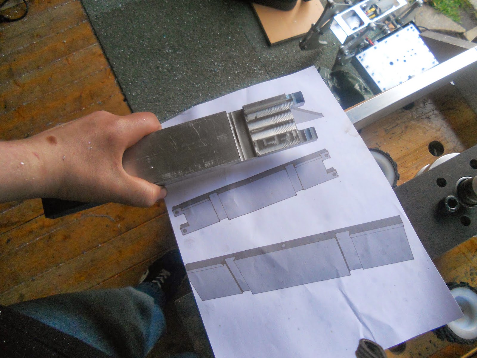

*shudders* I am so ashamed of that horrible mess. I shall attack it with some sandpaper to try and get it a little bit nicer. Here come some shots of the frame fitting together.


This should mean a really rigid frame. Hopefully at least. Still LOTS of places to remove weight should I need to. In case you were wondering how the motors fitted in this.


Will be carving more aluminium up over the next few weekends and days off from college. Lots of progress can be made if I go at it proper hardcore like.  I drilled and countersunk some holes in the bulkheads for where the bolts that attach the front brace go. M8 x 40. Also a picture of the frame showing off the finger joint a bit more.


I think that should just about cover my progress so far. Bit of a tiresome read if you did indeed go for it. I've had to be in college and be paying attention these last couple days but everything is now ordered for this robot and its signed up for the UK championships. Time is fucking tight as. But I'm having so much fun.
Cheers, Haz sXe

Tuesday, 25 February 2014

Massacre build 3

Being more than a little bummed out with college and trying to figure out what direction to take with my life (can someone pay me to build things for them??) I needed to do something I enjoyed lest I go mad and murder everyone with scientific calculator.

Some parts of Massacre are very designed, while other bits aren't. I purposely did this to allow for reality to kick in as what works in my CAD and in my head may not be transferred to the real world. Designing on the fly always seems to pan out better than relying theoretical stuff. For me anyway. One of these parts was the Rangleboxen, which is angle grinder gears shoved into a prettier case a right angled gearbox for the weapon. Because running 2.4Kw through shady £4 Chinese gears is a good idea right?
Now for my next trick I shall attempt to turn this pile of components into a fully functioning gearbox for a remote controlled death machine. (AA batteries not included)
Chopping up some 10mm 6082 aluminum with a hacksaw because I am too poor for a bandsaw hardcore like that.
Ewww, non machined edges. Quickly someone mill that thing!
That's better. Skimmed it down to 50mm high, its 100mm long here; I then shortened it down to 60mm long. Also featuring is wundermotter and an array of measuring tools
After the digital calliper was press ganged into service as a ghetto lay out tool and a screw as a centre punch (wow such precision, much engineering) I had super legit markings and could go and bore the holes on the milling machine. WTF is up with brushless motors though. They all boast eleventy bajillion watts and infinite torque but then come with M3 mounting holes. Using M4 atm and may step up to M5 for more hardcoreness.
Vanity pic outside where the light was better. It wasn't raining for once but everything was sill a bit damp and very muddy. Trying to match up to my buddy Ellis with the legitness of our motor mounts. His is 5mm aluminium and nice and curvy with 12.9 high tensile M3 for added poshness whereas mine is a big bastard at 10mm thick legit aluminium with M4  bolts. Only stainless so I loose points there. I will be doing more work to my mount, M6 mounting holes and will try and put a pocket in so I can sit the motor further into the mount for strength.
Ghetto machining time. The boss on the ranglegear was being a right pain in the arse. Some silly non standard diameter OD so I couldn't fit a bearing over it. It was also too long and would have sat the entire Rangle assembly up too high which would have put the blade height up. Unacceptable in a silly low overhead bot.  A simple solution would have been to turn the OD down to say 17mm and stick a bearing around that. Super low profile. But to do that I would have needed a lathe and Ellis was too pussy sensible to want to do mystery hardish steels with a machine that isn't totally rigid. So my other option was to lop a couple mm off the bottom of the boss on the mill. It's shit like this why I'll never be an engineer.
Crap photo but you get the idea. How are you gonna make the bearing pockets without a boring head Harry, they are kinda important? Well person who is not me, the sensible thing to do would indeed be to buy a boring head and use the right tool for the right job. But that is quite expensive (promise I'll buy proper things soon) My plan is to beast out most of the material with a big fuck off drillbit, then ream the hole to 26mm. <£20 solution and it should sort of work. A bit. Maybe.
Back to H4XX0Ring up the aluminium. This time 15mm thick 6082 which is what the robot is totally made out of because who needs underweight robots amirite?
The two outer bulkheads rough cut. A few years ago this would have been job done. Ah such memories. Now to shoehorn these bad boys onto a hobby sized milling machine! *dreams of Bridgeport*
I worked real hard to contain the maximum amount of cringe in one picture. Proper machiney people have probably vomited in disgust at this point.
Thankfully I didn't died. I still have all my fingers and now have a slightly more robot shaped robot! Luckily all the rest of the work can be done in the vice and doesn't require any massively dodgy setups. No more angles for me. Box with a weapon from here on in.
Pretend-O-Bot evolved. It's still 30mm wider than it will be but it has the beginnings of the wedge now. Temporary shafts in place still. I like this robot. The lowness is really appealing. Its made it a right pain though. speaking of which...
Why are the drive motors covered in masking tape? Harry? Well due to the small wheels and general lowness of the frame, I only had a few mm of ground clearance, which in a real world situation is a bad idea and would leave me grounded if the floor panels got bent up or there was a lot of debris or shrapnel in the arena. How to gain some ground clearance without major changes? Hmm well I could pocket the base plate so the motors sit lower down but the baseplate is hardened steel. Basically unmillable for me. So I had to get real creative.
harry... wut r u doin... stahp..

Yeah so I'm milling my gearboxes, all the cool kids are doing it. Don't judge me. There is an unnecessary 2mm or so of material that can go without any adverse effects to operation. Good enough for me!
For this I had to bust out my cutest set of parallels. Big hand for chibiparralels everyone.
Well, somehow this actually worked. No idea how or why but it did. I take that as a good sign for Massacre. Done all 4 motors without any hitches. Quick blast off a battery shows they work as new.

Well that's it for now. Long and very picture spammed but it could be interesting or useful if you are that way inclined. I'll post again when I've done something else.
Cheers, Haz.