Quite a large amount of work happened on the gearbox, and the prototype is mostly done. I learned a lot of stuff while working on it that make me more confident for making custom drive for my featherweight.
I always wanted to better support the end of the drive motors, although I've been lucky enough never to have problems in a robot because of this, it is an issue I would like to avoid. The fact that it looks cool as fuck and makes me look semi competent are total bonuses. In his infinite lathe wisdom, Ellis made me up some standoffs which attach the motor support plate. Picture credit goes to him as well.
Ellis and his family were good enough to put me up (and put up with me) for a week so some nice pulleys, standoffs and some epic weapon bars got made for me. I had great time in truly wonderful company and got some brilliant parts too.
We visited a stock place... Wow. So much cool and useful shit is sold there: nylon, stainless, steel, brass and aluminium. Not super high grades but still. Cheap material. I bough some 50mm aluminium round (classing it as "Probably 5083") and 500mm of 80 x 10 flat aluminium bar and a 500mm length of 50mm black nylon for about 25 euros. Roughly 20 quid in real money.
I got Ellis to make me some hubs out of the nylon I bought from the stockist. He cleaned up the faces and then did the rest of the work in a mandrel. It is pretty incredible how he is able to get parts concentric and can consistently hit half thou tolerances on the worlds worst lathe.
Spaming pics I know but some lathe work will make a change from all the gimpy mill set-ups I insist on documenting. Apologies for phonepics and the odd orientations. I didn't think.
The swarf the nylon produced was horrible. I nicknamed this the weave of death. Seriously horrible stringy hairy stuff. The nylon seemed to finish nicely with a heavy enough cut.
My hubs all complete. Horrorshow. Nearly all perfect except the countersinking on one side of the bore because of some dirty chattery 3 flute countersink.
Because Ellis is hella legit, he took some sweet photos of everything that got made. Nylon hubs, some nylon antweight pulleys, 4 6082 aluminium beetleweight pulleys, some standoffs and 2 beautifully handmade bars.
Super cool stuff. The bars are seriously nice. The stainless bar to make them was literally only a few euros. I vaguely poked dimensions and got handed back a seriously nice bit of kit in return.
Some pictures of the hubs on the motors.
More interesting things will happen sooner or later. Got a passable drive and weapon solution drawn up for Massacre so I shall stick up progress on that when it happens.
Only just got round to finishing what I started on the gearboxes, finishing up my first year of college and starting at a new job kinda sucked a lot of my free time up. Not complaining as those are both very good things. Next year at college I should be actually be allowed to make things (things other than a plumb bob) and hopefully spend some time designing and making robots.
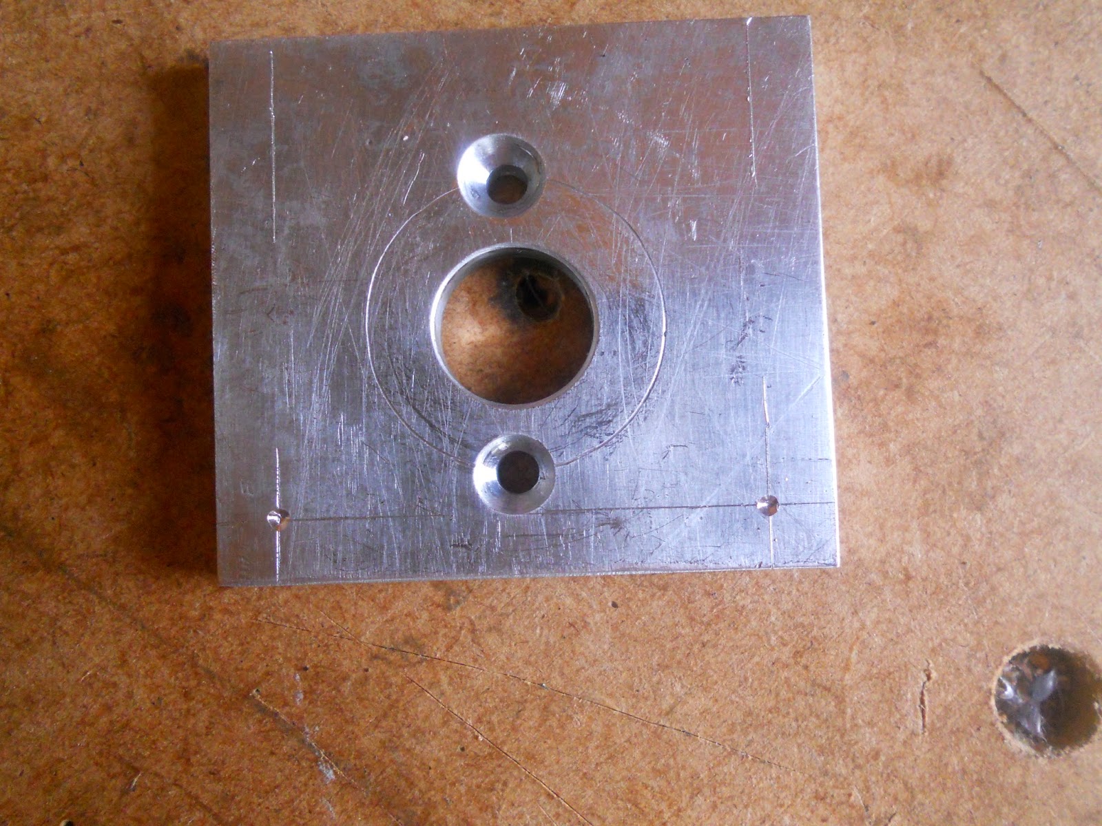
I'm big into quite heavy scribe lines at the moment. Normally with my parts only one side needs to be pretty so I can go to town. I centre punched the holes...kinda.. okay not gonna lie I used a screw and hammer then just started the holes with a hand drill. If you wanted proper machining techniques you're in the wrong place.
You can sort of see that one of the holes for the motor mounting is kind of a little wonky. Not to worry though it seems to work okay.
Did some scribing on the body of the gearbox too. "Centre punched" those too. I don't think you can see that in the photo or maybe I did it after taking this.
Drilled the holes on the motor plate. Used my neato little clamp my Dad bought for me to hold it down. I find its really useful when you have to do a few holes in the same thickness material. Managed to get the holes pretty much perfectly positioned. I don't know how I managed anything before drill press.
Drilled more holes into the main body of the gearbox and tapped those out to M5. Only did one side's worth of holes as I want to add a motor retaining plate but I'm not quite sure how I want to attach it to the rest. Also I had no idea if it was going to work and 2 wrong holes is better than 4.
It looks pretty good to me. Stuck it together with a couple of button head stainless M5 bolts.
3" banebots wheel on for the hell of it. It doesn't work like this as there is another stage of gearing still to be put on.
Ran it on one of my cheapy ESCs. It doesn't sound too pretty which is a bit of a bummer. However the motor doesn't get hot, nor does the controller. I think with a bit of tweaking it should run happy.
It seems a little "meh" but that is partially due to the unhappy gearbox and the fact it is an 18v motor run on 12v. For the first time in years I might actually have to buy a cordless drill or two to hack apart for components.
I've got a beetle or two in the works at the moment, but will save all their content up for a single post instead of stringing out dribs and drabs.
Going to give up with the standard "omg lel so much random topics" opening I tend to go for, just assume its going to be misc content unless its a hardcore build of one set thing, e.g. Massacre.
I was getting thoroughly bummed out by college and education in general not letting me learn or make anything. Luckily this conceded with me realising I had some money put by and therefore I could purchase shiny new toys!
First up was some cheapy chirpy Chinesey ESCs. I got these particular ones on recommendation from another roboteer who bought a few types of generic RC car "320a" (lolno) and tested them to destruction and found which was the best type, apparently it was this one. These should be fine running a 550 can motor on 3 cell in a 6kg robot. Normally the problem with these types of things, they don't have instant reverse. Quite understandably as they are for RC cars which don't really need to.
These do, hooray! That lipo in the video is munted, only about 8v or so hence why it's all a little lack lustre. I'll sort out some proper wires for the ESCs, get rid of the horrible Tamiya plugs beef up the heatsink and I should be laughing. The cost of these things? £10 each shipped. Luv u China.
Tooling tiem now. I love the mill to death but it is a little lacking in tooling. Facing 50 and 75mm stock with a 12mm endmill is not fun. It is time consuming, and with the generally hobby-ness of the machine it can be pretty damn inaccurate. I bit the bullet and got a face mill.
3" face mill with carbide inserts. Yay legit insert times. I can't stress how much I needed this and now much I adore having it. The quality of the tool is good considering the money, the thread for the drawbar was a little stiff but its loosened up nicely now. Other than that it is excellent. The maximum face mill size recommended was 2", but what's an inch between friends? (oo-er missus) I figured that it wouldn't immediately be a problem, and it was more the manufacturers covering their arses. Either way, it cuts fine and it hasn't killed me yet.
A wild boring head appears! Really nice little 50mm boring head. I got this so I could finally be free of bushings and start putting legit bearing pockets in things. 0.02 increments. Also got a set of brazed carbide boring bars ranging from diddy little to bastard big.
Its funny to think I can now justify £130 two tools, one to make things square and the other to make round things. What happened to hacksaws and 10 quid holesaws??
With my new nice tools I began to hack up an ESC box. This will be made up of several layers of chopping board stacked up to 40mm thick and carved out to house 2 escs. A 5mm aluminium lid will add some strength, protection and also act as a heatsink. This is totally unnecessary but it's fun, free and gives me something to do.
Rough cut the blocks by hand. Was able to stack them all together and get them square at the same time with the greater reach of the new face mill.
I then took some meat off of the face of the material to get a flat surface. The stock chopping boards have a bobbley finish and vary in height by about a millimetre or so. I then gave up. I'll get back to it later. Promise.
Now here is where we get a bit more hardcore. I won't harp on about Massacre's drive because frankly nobody cares (although that has never stopped me before) All I will quickly say is it's becoming more bitsy like its weird gimp of a cousin Rango, built by the equally weird, equally gimpy Elvis.
Its a thing.
In the age of people wanting to put 2kw brushless motors and 10s into their drive systems I go against this by not only sticking with my lovely 550 drill motors, but reducing their gearing. Punk rock engineering! Fuck your trends, robotics! 15:1 and made out of China gears and hope. The RangleBox Drive makes use of cheapness and my current tooling to hopefully produce, if nothing else a cool looking drive setup. It also reduces space taken up by things and gives me neat places to organise ESC and wiring. Ignore the bushings. I designed this before I got the boring head. My original plan was to get the aluminium part that held the first stage of gearing CNC milled. Realising I could get a boring head for about the same money, I elected to do it myself.
Rough cutting out the 5mm aluminium motor mounting plate. Don't worry the holes are supposed to be off centre. Alu is 6082 (whole gearbox is) for anyone who cares. I can't afford 7075 don't judge me.
Milled to size and beginning to be bored out to 13mm. Just as a test before I get all hardcore with the proper bearing fits.
Finished boring. I need telescoping gauges and a micrometer now I think.
Yay I made a thing. I then gave up for the day, ending on a high as I find it starts the next day better.
Cutting some square bar stock for the planetary stage. As a fat guy on a hot day, cutting 2" alu by hand is an unpleasant experience. Alas, I must suffer for my art.
Managed to slice it off pretty straight in the end so I didn't loose that much material. I then faced it to size. Nice thing about using 2" stock and designing to 50mm, you get to tickle like .3mm or so off each side to give a machined finish.
Got the stock near enough to size. Then marked it out for boring.
Please excuse the pigsty. I'm a teenager, its genetic.
Well, it looks like it should so that's something, right?
Having the bearing fit perfectly into the pocket was a really good feeling. A job done well is its own reward I suppose.
Ring gear pressed in. Made it a really tight fit, it was a few thousandths under. I can put a retainer on it to stop it slipping. But even with the hardcore power coming from a 550 motor it should be fine. Testing will show.
With carrier and planet gears. Looks too fancy to be a part made by me if I do say so myself.
Pushed the first stage of the gearbox up onto the motor mount. Really pleased with this so far.
Welp, next will probably more gearbox related stuff, or just more box stuff.
The title makes it sound like stuff happened. It didn't. I started a few odds and sods and documenting them helps me to get my thoughts in order.
I'll start off with a continuation of raptorweight (6kg) thoughts. Going abroad for a comp isn't going to happen super soon because money and inclination are both in short supply. I threw some ideas around, coming up with two stupid vertical spinners which were rather beyond budget at present moment. I then dropped this to a silly fast wedge. Tentatively diving into custom gearing to give me 20mph. 5/8" 6082 aluminium frame and a 4mm mild steel wedge which I designed to be watercut, scored and bent to shape then a weld run inside the bent to strengthen it. This would be cheap, as I would only have to splash out on one part, the watercutting hence why it was a fancy method instead of just buying plate and hacking it up.
This idea died a death when I bought a 6mm wall aluminium tube. Drum spinner tiem.
Dicking around in CAD allowed me to stick a counterweight inside the drum and get it balanced. Shot to sorta kinda show what I mean with some rectangular steel stock. Neither machined to their sizes yet.
This is the kinda shape I was after. The slanted back gives me a nice airgap to protect all the gubbins with. I wouldn't be able to have that with just a flat Dominant Mode shape. I'm not skilful enough to survive with my haphazard internal space management and a design like that. Robot is kinda tiny, more so when you realise that the wheels are 60mm.
4wd is fun, but 4 motors is hassle and too much weight. To solve this I had to figure out a good way to link the front and back wheels together. Space was a premium as always. Thin HTD timing belts will do. I wanted a dead shaft for the un-driven wheel for strength and also because I can't do bearing pockets due to chronic lack of a boring head.
Now instead of just sticking a 3/8" UNF tap into some hubs most UK people seem to prefer getting some nuts and just using those pressed into wheels. I am no exception, I used insert nuts for Massacre. I got a pack of like 10 or 12 for chicken feed and I might as well keep using them. I began experimenting.
First, using an incredible display of ghetto engineering I threaded the brass nut onto a cut off drill shaft (blackened because I'd been using it to heat-press the inserts back on Massacre with a large blowtorch) and stuck that drill shaft into the chuck. I mounted and squared up my workhorse vice in the mill and ran the nut/shaft assembly back until it touched the far jaw of the vice. Tightened it up, locked the table down and took the shaft out of the chuck and put it to one side.
Then I hogged out most of the meat and the threads with a 9.7mm drill.
Then with pure unfiltered bodge I ran a 10mm endmill (that's right, endmill) through the bore to get a legit 10mm bore. It ended up being about 10.08 which is pretty perfect. Considering the questionable techniques and my traditional wanton regard for tolerance it's great!
I forgot how to camera so it's slightly more blurry than a bigfoot photo. Sorry.
Brass nut made into a Pretend-O-Bushing. Not as good as a sintered steel or bronze bushing but cheap quick easy and with the life and abuse of robot combat I doubt it will have that much effect. I'll keep it lubed and if there is a problem later down the line I'll fix it then.
Then I decided to get the nut mounted into the hubs. Heat pressing is so last month. I thought I'd see if I could use my manly brute force and clout to get them in.
The bore is 14mm and the insert is 16.5mm-ish point to point. should make for a strong connection.
Man I love my press vice.
As you can see it was a pretty perfect fit. Straighter than all my heat pressed wheel. Fair amount of crap got pushed out with it. clipped it off and it was ready to roll. Tried it out on a bit of precision ground steel (countersink shank) and it span nicely.
Great stuff.
Next we have a look at slight upgrade/improvement on the mill. As you've no doubt seen in some photos I tend to work in chaos a little bit. This isn't the best when I'm working with more legit tools such as the mill. I hate having all the swarf and chips everywhere and without a propper T slot cleaner its a pain in the arse to get it nicely clean. I set out to solve this by making more of a mess making some bed guards.
Simulation of what I want. It's always a good idea to make parts for your precision machine out of second hand skip steel. I got a few of these sheets donated by Tweedy, another feather/beetle roboteer.
Got to play with the angle grinder again. I quite like it, being an aluminium and plastics man myself. Must work with it more often.
Shoved a 1/2" hole through it. No need for uber accuracy. Again, steel is nicer to work with than I thought.
Is finish. No more crap in the T slots. Although this setup only really works with my workhorse vice not my nice toolmakers one, still good.
Also in steel related news, I finally got my arse into gear with wedge making for my 4wd drive all day beetleweight lump thing. It is just 10mm plastic and 6mm aluminium frame with 1mm stainless and 3mm polycarbonate base and lid. Something to lumber itself around and not break. So far has worked great. Had a bit of aluminium L angle as a scoop before but that fell off because rubbish attachment.
Marked out and cut me some steelage. Yum. Wedge is pretty meaty because the rest of the robot is 900g, 950g tops. Big wedge and maybes going 4s if need be should make it super wedgy, bricky and anoying to fight.
It got scored where I wanted it bent. Then once it was bent to the full extent one score would let it I scored it again and got it to bend a little more while keeping it smooth and nice looking. Briefly twatted a protractor up against it to check I could get the bends within a few degrees of each other. #precision.
Doing the second scores.
Pretend-O-Bot. Still got a ways to go in the wedge, and hinges added to it. The wedge is 420g. So it puts the weight up to about 1360g. Horrorshow.
Yo dawg we heard you like vices. This is how I decided to try and get the wedge flat to the floor. A more sensible man would have ground it, but I only had cutting discs so nowt much could be done. I think I could do with some carbide tooling as I cattled a 10mm bit doing this (User error may be the cause) . I only have one carbide tool and its a 3mm slot drill. I'll look up prices for 8-12mm carbide endmills at some point and probably cry at the prices. I also need to look at prices and brands for 3" face mills. Hopefully I can get one for around £50 or so but that is very hopeful.
Aside from some Massacre CAD that's about it really.




.JPG)


