First off I set about doing some of the work on the main bulkheads of the thing. Because I am not the greatest designer in the history of things, I had basically mounted half the components inside other parts and the whole setup is extremely mill intensive. *sigh* This is the part where I realise past Harry who did the CAD sort of forgot how real life works. Anyway, here are the blank side bulkheads before I did any more machining on them.

Marked out the aluminium in a ever so slightly ghetto fashion as I am prone to go, and then got cutting metal!


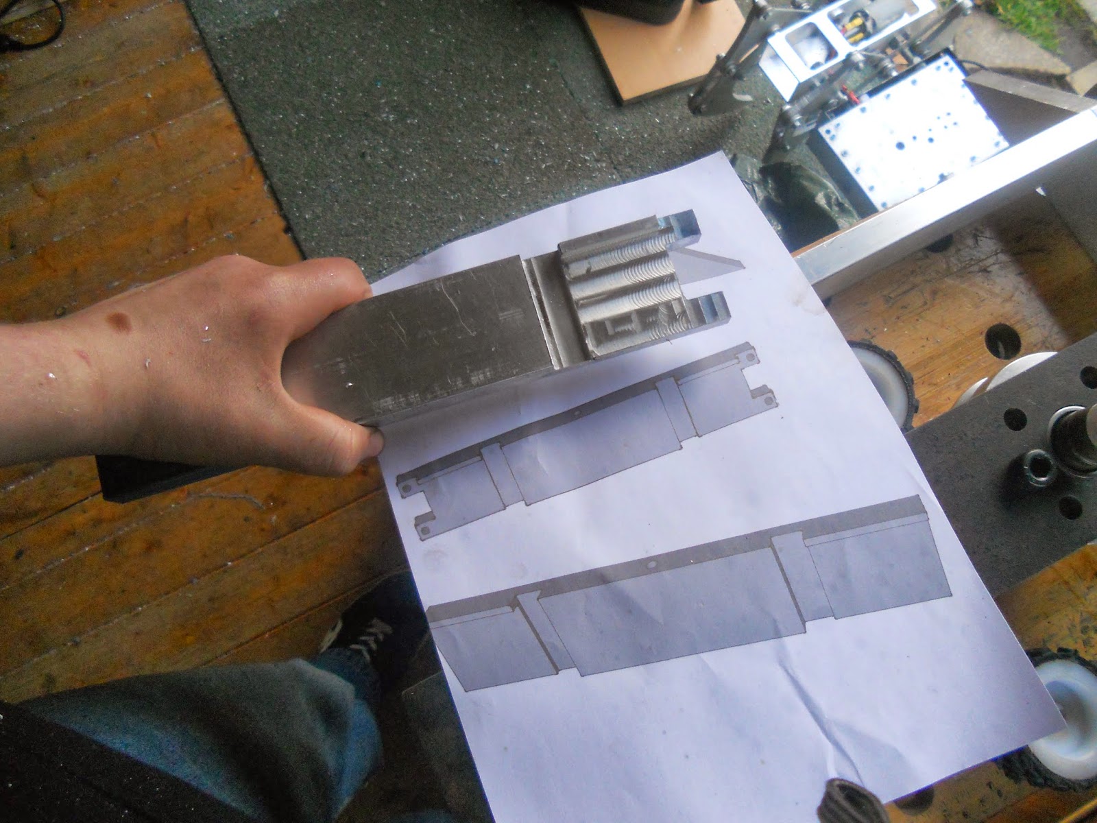
One of the bulkheads with the finger joint done on the back and the recess milled. I did this all with a 12mm endmill as I didn't have a 5/8" endmill in my bucket of odd imperial tooling.

More parts. Rubbishy photos due to this being quite late evening and me generally taking naff pictures.

Pretending to be a real robot. Also in this picture you can see random lump o metal, a battery operated soldering iron and a sky themed robot kindly donated by Joey. Who is six parts wonderful, incidentally.
And this is where the post started coming. It was like Christmas, except with less socks and more bushings.

Shaft collars, roller bearings, bushings, ball bearings of all sizes, threaded inserts, BOLTS, 24v LED's and a thrust bearing. Oh and a fair amount of silicone wire.


The reasoning for why I have both bushings and bearings will be explored shortly, although the conclusion is not at all justified/satisfactory to any sane human being. The brass things are 3/8" UNF nuts which are the same thread as drill motor shafts. I plan to heat press these into the nylon hubs that Ellis made for me to make


Mocking up seems to be a good 60% of what I do when I try and build robots. Here you can see the horrible milling that happened on the back panel and the vague wedge shape.
Continuing with the theme of post and packages, more stuff arrived the next day and some very exiting stuff it was too. First up was this mysterious package that had some crazy foreign writing and the inability to spell names on it. Bet it was that tricksy hobbit Elvis.


Ok now we talk about the bearing/bushing situation. Basically I couldn't pick. The bushings are much more tough so that would be good for the weapon, but at the same time would have more resistance. Bearings are smoother but weaker. CHOICES HOW DO I.

Yep, that works. I managed to find bushings and bearings that had the same id and od, although different lengths but not by much. They fit the pulley nicely. Sweet.


And here we have some uninteresting visual stimulus. My big fuckoff bolts for the weapon, 12.9 high tensile cap head M10's. Six of those should keep the bar attached to the hub. Also featuring are some XT90 connectors I picked up for a few quid on eBay. These are for the removable link. They are large enough to take the current of the system but are fairly difficult to pull apart, a desirable quality.

A mysterious bar shaped package appeared! I wonder what it is? Maybe its a really heavy and ornate hat?

Nope


And here we see me Pretend-O-Weaponing with the bar. Everything seems to be on spec thus far!


Bearings fitted in pulley and in bar for super legit alignment technique. As per usual proper engineers or machinists should look away lest they have their eyes melted by the horrible bodge. You have been warned.


Voilà, one hole, hold the mustard. Now on to tapping the thing out to M10. I elected to drill and tap all the way through because A, no proper ways of knowing hole depth (not without monkeying around with stops on the mill etc) and B, I don't have a M10 bottoming tap.


I managed not to break the tap or cattle the pulley! Where's my prize? On to the next hole.


Mocked up weapon assembly in the last picture. Spins very smoothly by hand. Also I use the one 15mm wide timing belt I had to hand to check the groove. It's a weird belt it is "not-quite-5mm" pitch. Fits real nice. Ellis did a sweet job on the pulley. Although I think it was a major pain to do on his none to rigid lathe.

After the gratuitous weapon excitement I turned my attention back to the frame, because its kinda important. I Sorted out the finger joints and slots for the drive motor to sit in. The finish is abysmal because I did it in a totally stupid way. Luckily this part will not actually be seen, he says as he posts pictures of it on the internet.
*shudders* I am so ashamed of that horrible mess. I shall attack it with some sandpaper to try and get it a little bit nicer. Here come some shots of the frame fitting together.


This should mean a really rigid frame. Hopefully at least. Still LOTS of places to remove weight should I need to. In case you were wondering how the motors fitted in this.

Will be carving more aluminium up over the next few weekends and days off from college. Lots of progress can be made if I go at it proper hardcore like. I drilled and countersunk some holes in the bulkheads for where the bolts that attach the front brace go. M8 x 40. Also a picture of the frame showing off the finger joint a bit more.


I think that should just about cover my progress so far. Bit of a tiresome read if you did indeed go for it. I've had to be in college and be paying attention these last couple days but everything is now ordered for this robot and its signed up for the UK championships. Time is fucking tight as. But I'm having so much fun.
Cheers, Haz sXe
No comments:
Post a Comment